This Telerad 23 inch set Model 35 that was built around 1962/63 is something rather unique and special.... Its unique because it is a very rare low production model and this would be the only one left in existance and its special as the person who designed and built this TV was known by me personally.
Here is some background information on Alan and his manufacturing history:
Alan was a very clever man with an amazing brain for knowledge and was very switched on when it came to anything technical or electronic.
He started making radios back in the 1930’s and all of his sets were manufactured from his home, and a large area of the house was used solely for making them. His brand name was called “Telerad”.
After the Second World War, he returned and continued to make radios including hi-end HiFi amplifiers as audio was one of his passions, all of his radios had a very well designed audio section and the sound quality left any other locally made set for dead.
I have a couple of his Telerad radios and they really perform well with outstanding sound quality.
I can’t remember when he stopped making radios, think it was the around the mid 1950’s but his HiFi amplifiers were still being made though.
Alan always followed the latest technology so naturally gravitated towards television when it started becoming the latest craze in the electronics industry.
I met Alan in the early 1990’s as a teenager through the local radio club. I used to call him regularly to ask technical questions and he didn’t mind as he could talk for ‘hours’. You had to listen to an hour or two of his war stories first but then he could be easily diverted with an electronics question so he’d rattle on for ages about his designs/circuits and the things he made and would answer the question in between… He was a talking book and I wish I had recorded some his phone conversations as they were dam fascinating.
His health slowly began to fail in the last few years of his life but his mind was still as sharp as a tack.
Alan died on July 7th, 2007 aged 94.
This TV came out of his house, it was buried in a back room with stuff piled on top of it. He became a hoarder in recent years and the house was ‘full’ of test gear/valves/components/radio cabinets etc. Unfortunately some of it was dumped but a lot was rescued and found new homes. I got about six Tektronix scopes, heaps of components and some other bits and pieces including three brand new unused radio cabinets for my Telerad sets.
The internals have been made up using left over radio components from the 1940's and two radio chassis stuck together. Alan was not one to waste anything, he never threw anything out.
The tuner and line output stage are all Philips, so is the picture tube (Miniwatt AW-59-90) and deflection yoke.
It is hard to believe that this TV was made in the 1960’s as the chassis/valves/components looks like something out of the 1940's/50s! This is one very fascinating TV indeed.
Here is the valve line up, the majority of them are octals: All I'm going by is the hand drawn valve location chart that was taped to the back cover.
Tuner ECC88/ECF80
1st IF 6SH7
2nd IF 6AC7
3rd IF 6SH7
Sound IF 6SH7GT
Sound Det 6SQ7
Audio Amp 7C5
Video Det 6AC7
DC Restorer 6SA7GT
Peak Detector 6SA7GT
Sync Amp 6SA7GT
Sync Sep 6SH7
AGC Gate 6SA7GT
Line Multivibrator 6SA7GT x 2
Vert Osc 6SA7GT
Vert Amp 6L6
Line Output EL36
Boost Diode EY88
EHT Rect DY87
So there’s quite a mixture of valves there and he used a lot of 6SA7’s
Also a Rola 12 inch 12UX dual cone speaker was used for the sound, the one shown in the photo is not the original. I have the original speaker for it. No doubt the sound quality will be excellent from this.
In regards to the circuit diagram, well there isn’t one and this is going to make the repairing/fault finding/restoration a lot harder! I can see head scratching/frustration and swearing in the wind with this one!....
But fortunately I do have a complete spare chassis so this is going to be my only saving grace.
I have no idea what circuit design he based this on either so its going to be an interesting journey bringing this set back to life.
He put a note in the set saying it was last run in 1987 and that it has a horizontal sync fault.
When I got this back in 2007 I found the main filter caps had leaked out and the terminals were eaten away so I temporarily wired some filter caps in and replaced the rotten power cord… I never did get around to putting any power on it though. Everything else looks ok underneath and I’m toying with the idea of slowly bringing the set to life with the variac and seeing what happens.. I know this is a bit risky but at least if the set show signs of life I will then know what stages are working and as I don’t have a circuit it maybe the only way to get voltage readings etc. Hopefully the picture tube and lopt are ok.
Since typing this up well over a week ago I have tested the CRT which is good and slowly powered it up using the variac and the final result was a blank raster which means the flyback and vertical circuits are operational, see the photos below.
25/6/2011 - I have started changing the .1uf Solar caps in the EHT section, they all tested leaky so it will be good to change them all eventually. It currently has a video/IF fault which I'm yet to fix, will start with testing the valves first.
27/6/2011 - Some good progress has been made, the set now has an actual picture! After some fault finding what it turned out to be was a filter cap that supplies the HT to the video stage had gone shorted on one section to ground. I put a temporary cap 10uf 400v in place, switched it back on and now had snow, connected an antenna and hey presto a picture! See photos added.
There is a problem with the horizontal hold, its dam touchy and it doesn't take much to make it lose sync. It was an historical moment in a strange way really to finally see it working to a degree after 24 years even with its problems!
I also tested all the valves with the PACO and found all the 6SA7's were weak, I also confirmed this with the AVO Mk 4 VCM to just be certain and they all had low anode reading and very low ma/v readings. I had some NOS Kenrad 6SA7's which came from Alan's estate so all seven were replaced with new ones.
So will now continue on replacing caps and checking resistors with power ups in between.
4/7/2011 - Progress Update - One section has been totally recapped and most of the resistors have been replaced. Some checked fine, others were way off.
The area I did was in the horizontal drive/osc/sync section. The horizontal sync is now stable and the picture locks in perfectly.
I have to admit that some of those old components were a little tricky to get out, some of the caps were buried underneath others, thankfully I took up close photos and drew some rough diagrams so to resolder all the new parts back in the right place.
I also checked those mica caps just to be 'sure to be sure'...They all checked fine.
Have now started on the vertical section....And that's where I'm at to date. See recent photos.
13/8/2011 - Update (Photos added) - The vertical section has now been totally recapped and all resistors replaced, most of them were way out of spec and the result is now a nice even picture that fills the screen. I can adjust linearity and height now without any problems.
I also tidyed up the smoothing cap arrangement in the voltage doubler circuit for main B+ that runs the whole set.
I actually had some identical new old stock filter caps which reformed to near perfect so I installed those, they should be ok, even though the filter caps are old, and generally I'd just put new ones in, but in this case I thought I'd try them and see how things go. I will replace rectifier diodes but for now they can stay there.
I think my next move is to replace all the electrolytic caps that are still in place and there are about 1/2 a dozen or so.
Since the original speaker was missing I temporarily connected another speaker that had an output transformer with it and tested the audio side and thats working fine too, there's no video buzz or off tune noise and sounds good, so the alignment has held up pretty well. At least thats something I don't have redo! That's all for now.
I also have some videos about this set on YouTube, here is the link -
http://www.youtube.com/watch?v=yVfKiW_1_BI
21/1/2012 (Photos Added) - Well, this restoration project is now coming to a close, the set is almost done.
I have been slowly working away at this over the past five or so months in between other customer repairs and when time has allowed. It's really been in the past month or so that I've come this close to finishing it.
All electrolytic and paper capacitors have been replaced along with several resistors, some where way out of tolerance, others were still acceptable but I changed those anyway just to be on the safe side.
It now has the original Rola 12UX speaker all wired up with a decent output transformer and the sound quality is excellent, full range with plenty of bass. I also fitted a mains fuse and renewed the power switch mains cable as the original had crumbled away. It was cut out and bypassed while working on the chassis. Also changed the horrible old screened cable from the tuner to the 1st I.F.
I didn't try to clean the chassis in anyway apart from getting rid of years of dust as it only has been sprayed with silver paint and I didn't really want to disturb it or put something on it that might cause problems so have decided to leave it as is.
But this whole process was not without its problems I encountered two rather erroneous faults in both were not caused by capacitors.
Fault 1 - From cold the width control worked and the picture could be adjusted to suit,
after about 5-10 minutes the width would increase in size and get to a
point where it was excessive and the boost voltage would rise with it which I didn't like so set out find out what was causing the issue.
After checking/testing and replacing the obvious, in the end it was width control pot that was causing the problem. Obviously heat/voltage and age was
causing the resistance in the pot to change after time. Luckily the pot on the
donor chassis was ok, so I put it in and now the width controls works and the picture and boost voltage
are now stable - phew!
Fault 2 - This one kind of led me on a wild goose chase in a way, after about 1/2 hour I noticed
the contrast would reduce and picture would get a bit washed out and I
had to adjust the AGC control to compensate as it warmed but even with the AGC pot hard
at one end it still wasn't good enough.
I started with the tuner and did find a 5.6k inside which has risen to
about 20K, but that didn't fix it so started poking around with the
scope and confirmed that it wasn't the front end causing the problem.
Next I moved to the AGC gate/sync area and eventually found a 22k
resistor that was heat sensitive, spraying it with freeze would
restore the contrast to normal but as the faulty resistor warmed the fault would return again.
Something interesting to note that while
it was faulting, touching anything around there with meter probes would
boost the contrast level, but after the new resistor was put in, this
had very little or no effect, must have the capacitance of the meter
probes compensating for the fault!
This one did take a while to find as I was thinking it was a valve or capacitor and maybe I'd rewired something back incorrectly but this wasn't the case.
So there you have it, TWO faults caused by bloody resistors! Now I'll stop assuming these things are fine in old sets - Suspect Everything!
26/1/2012 - (Photos added, scroll down) Its done!! The Telerad is finally all back together in its cabinet and is complete!
I have to say though its been an interesting project to say the least
and it took me a lot longer than I'd expected to finish it and I learned
a few things along way as you do with anything like this. The bit I
didn't like was not working without a circuit, there's always a degree
of uneasiness with something as rare and odd as this, but thank goodness
I did have that spare junk chassis and the heap of photos I took to
fall back on especially if I'd undone a part of the circuit to replace
some components and then left it like that for a week or two!
I also reckon that this Telerad was set number ten that he made as there
is a code on the back of both chassis, this one is '1510' and the donor
is '1503'.
Thinking back I do recall Alan saying he used a prototype set in his
living room for years and that one is the junk chassis as I saw where it
came from after it had already been thrown in the skip complete with
CRT etc and smashed by someone helping with the clean out at the time
before I could stop him!
Now I can sit back and enjoy watching it. There are a few DVDs I've been
putting aside just so I can see them on this, so looking forward to
doing that now.
Hopefully the set will behave itself, now its back together. The cabinet is really well built and does look nice.
I'm sure if Alan were still alive he'd be tickled pink to see his only remaining set in existence going again.
So in a way this is a tribute to Alan..... I'm sure we'll meet again some day my old friend.
Thanks for reading and following this blog, should anything else come up in
regards to the Telerad I'll post an update. Cheers!
 |
| Side |
 |
| Rear view |
 |
| Back cover removed |
 |
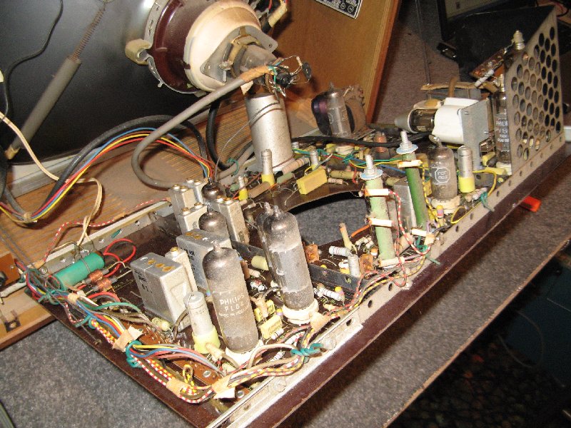
| Overall chassis view |
 |
| Mains transformer and vertical output valve which is a coke bottle 6L6! |
 |
| Close up of the chassis, note all the octal valves |
 |
| More octals! |
 |
| Line output/EHT cage. Philips Line output transformer was used with this design. |
 |
| Tuner/control assembly. Typical 1960's Philips tuner |
 |
| CRT brand/model Notice its made in Holland. He must have imported these tubes. |
 |
| Adjustments |
 |
| CRT neck/deflection yoke |
 |
| Underneath - Check out those 1940's resistors and capacitors! Very neatly wired though. |
 |
| Valve chart layout |
 |
| Initial picture tube test - Looks promising.... |
 |
| First time running since 1987 |
 |
| 27/6/2011 Off station snow |
 |
| 27/6/2001 No sync |
 |
| 27/6/2011 And finally a stable picture! |
 |
| 27/6/2011 All the dead 6SA7's |
 |
| 27/6/2011 Temporary 10uf cap in place |
 |
| 4/7/2011 Slightly improved picture |
 |
| 4/7/2011 Repaired Area |
 |
4/7/2011 More dead bits...
13/8/2011 - Vertical Section and main power supply B+ voltage doubler repaired
13/8/2011 - After repairs to date, a nice even picture
|