Tuesday, 17 April 2012

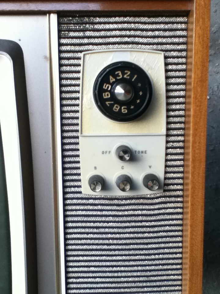
AWA Murphy 23" (34 Series) Super Signal TV ***Finished 27/12/2012***

I actually got this set around November of 2011 and kept on forgetting to put it up on here until now.
Its currently undergoing a slow restoration in small stages, time being the factor at the moment.

So far I've replaced the critical components in the flyback section, as all the wax capacitors were leaky and resistors were way off as well. Also the1B3GT EHT rectifier valve was also gassy so this didn't help things initially and there was also a brightness problem due to the picture tube being cutoff, cause insufficient grid volts caused by leaky caps so after fixing that it now has a picture of sorts.

This early chassis was based on an Australian design and was known as the '35' series and said to be a good performer. Several variants of this chassis were used in all AWA & Murphy sets of the time.

There are an awful lot of resistors and caps to be changed so its going to take some time. The mustard coloured resistors used in this are all way off, like the Pye T22X they will be replaced.

I've started a video diary on YouTube in regards to this set, here is the link -  http://www.youtube.com/watch?v=8CThn6yz8fE&feature=g-upl&context=G2c1cf0aAUAAAAAAATAA

Thats all on this one for now, I'll post with updates as progress is made.
The first few photos were taken with my new Ipod touch 4G at the time, image quality is ok, but the digital camera is far better.

8/6/2012 - Some slow progress has been made on this set, I've replaced a handful of components around the EHT/flyback section, all the resistors and low value electrolytics were well past their use by date, no wonder the width was lacking in size initially. Also worked on the vertical section as well, replaced a number of drifted resistors and leaky wax capacitors. So the result is now a watchable picture, not bad considering the rest of the chassis is still pretty much 80% original. So once I start replacing more parts, things should start improving. There is an issue with the top linearity, the control is at one end and thats the best I can get it for now, but no doubt theres another resistor or cap thats way off value.
So thats all for now folks! See the recent pictures added.

27/12/2012 (Photos Added) -  Finally this set is done! All cleaned up cabinet wise, fully re-capped and almost all the resistors too. The resistors that were in this were off and some of them had even drifted oddly enough to the next preferred value, which made me wonder if they were incorrectly marked while being manufactured...who knows? But at least they're out of there and won't cause any further problems.

The restoration took longer than expected, I just kept plugging away at it slowly so rather relieved that its come to an end.

But... I did have a couple of problems along the way...The first was intermittent hum bars that would come and go at will, at the time I thought it was just some of the old caps that were still in place, but after replacing all them and the rectifier diodes the hum bars were still there.

Scoping the B+ rails one of them clearly showed this 'blip' of noise moving along in time with the hum bar on the screen.

My next thought turned to the valves, thinking that maybe one of them had an internal short possibly due to the filament supply leaking AC across internally to somewhere it shouldn't be. As it turned out I found 'several' of them with multiple shorts the 6EB8 video output valve being the worst!
Once I replaced the crook valves and powered on again, the hum bars had vanished.

The next problem was towards the end of wrapping this up, I went through all the adjustments including the horizontal oscillator. Got that all done, had the picture all centered and locked nicely, powered the set on the next night from cold and found the sync to be way off.

After about 30 seconds the sync locked in again but the picture was way off to one side and I could see it slowly creeping back into line, after about 5 minutes it was normal again.

My thoughts about this turned to one of two things, faulty mica caps in the circuit as there were a couple and there was one in series with the hold control and the grid of the 6CG7 or the valve itself.

I changed that mica cap as it was well below its value of 330pf, this didn't really improve things so popped in another 6CG7 and problem solved!
So much for the original valve testing OK! I think in future I'll have some good know substitute ones handy for future niggly things like this.

So now its all back together and running very well, despite the CRT being on the weak side it still gives a very nice picture.

This is the first time I have overhauled one of these particular AWA/Murphy 34/35 series and have to say the contrast and definition is really good. I guess a good circuit design plays a part in this as well. If the picture tube was good the results would stunning I bet.
I've got two more variants of this to do so looking forward to getting to those eventually. They're both consoles and one of them is mint and low use so that should really respond to some work.

Now I can move onto something else, have plenty more to choose from...unsure what one I'll start on next... as for this one...The End!

Restoration Complete 27/12/2012. First photos and progress below.


Initial Look

First glance inside


Underside of the chassis...Look at all those crusty old resistors and caps.They're just waiting to cause trouble!
New boost capacitors installed. These are crucial to ensure the line output stage operates properly.
A picture of sorts...at least its working, well kind of!

 8/6/2012 - A far better picture than last time.

 8/6/2012 - Vertical section with some new components

  8/6/2012 - Components changed in the flyback/EHT area - I cheated with the old component legs and used wound sections of solid wire to solder the new ones into. Quite neat, I've seen in this some old Philips electronics.


Chassis all completed underneath. A mixture of NOS components and some modern types.

  The dead bits/organs

 Chassis all clean with shiny valves.

 Cleaned up cabinet and front panel/glass.

Excerpt from the original "Twilight Zone Series"


Thursday, 29 March 2012

Philips 23TZ323A 23" TV

This Philips S8 is another recent addition to the collection and since I already have three of these I decided to get this going to use in the workshop.
I found some interesting stuff on how the S8 was created, it was copied from a European design and here are a couple links to a website which shows the direct derivatives that the NZ version was based on. It seems to be a mix of two sets shown in Link 1 & 2.
Thanks to Marcels TV Museum for such a great website covering vintage Philips TV's and more.

Marcels TV Museum

Link 1

Link 2

Unlike all the other S8's I've seen or worked on this one still has its original line output transformer and virtually no dry joints on any of the valve sockets and hardly any damaged or lifted print on the boards which leads me to think this hasn't not had much use but it did take some work to get it working properly.

After replacing a busted EF183 and boost cap that had split open I applied power via the variac and raised it to 200 volts and waited....nothing much was happening so increased the mains some more...got humming from the speaker and that was it, did a quick measure of the B+ rails, which were all present but it no other real signs of life...hmm a bit odd as these usually were a bit more lively than this!

Started with the horizontal drive and found not much happening there so replaced the PCF80 and things started happening we now had EHT and a line across the screen! Done some more poking only find the vertical oscillator wasn't working either, another PCF80 later and now had a full raster.

But it was rather dead in the tuner/if stages with a signal fed in just a blank raster...Found the 2nd IF EF184 had no emission and a short, so replaced it, still nothing....I then checked the PCF86 mixer and PCC198 RF amp in the tuner and found the PCF86 to be gassy, it lit up pretty colours on the the AVO and got pulled out pretty quick.

So in went another PCF86, now we had something but still no picture just flashes of snow/lines and I just happened to knock the board around the 1st IF valve and that made the picture go nuts, so some prodding indicated something was loose here. A look at the board revealed broken tracks around the IF can and a shoddy past repair to the print.

I fixed all that up and tried again, there now was steady snow, so I rotated the tuner to the desired channel for the RF modulator output...still nothing... then the picture started flashing/pulsating every few seconds...What the hell was going on! I could now smell something getting hot and happened to glance down to tag strip on the tuner where the B+ supply resistors are and saw one of them glowing red so lunged at the kill switch on the variac!

Ok so buy this time I was starting to think nasty thoughts about this set (Mental images of pulling it off the bench by the power cord and laughing madly as it hit the floor!)... This was mean't to be a quick fix and now turning into a rather drawn out affair.

I checked for shorts to that stressed 560 ohm resistor to ground and found nothing so removed the tuner and pulled the covers off to investigate inside and a rather burn't looking resistor to one of the valve pins was staring me right in the face, ah-ha! The circuit called for 3.3k and this little charcoaled delight was reading 220 ohms. I wasted no time in replacing it, reconnected everything and applied mains while monitoring that supply resistor and to my disgust the 3.3k started belching smoke and the poor 560 ohm lighting up again like a tiny bar heater.
This thing was really starting to test my patience so I walked away and left the thing alone and just as well as that evening my wife went in labour with our second child so that put a stop to TV tinkering for the time being.

Once back on the job I went over my work done on the tuner and could not see or find any shorts within the tuner. I did have some spare tuners but my gut told me not to replacing the tuner only as a last resort. Then I had a thought about the tuner valves again wondering if the replaced PCF86 or the original PCC189 was faulty? So for a laugh I put in another PCC189 and tried it to no avail so I put in another PCF86 and tried it again...This time the voltage wasn't dropping and it was stable...so I waited expecting smoke, then sound burst forth from the speaker and then my test pattern DVD appeared on the screen! HORRAY!

So what the hell was up with that so called 'good' PCF86? A quick test of it again revealed several shorts, so why did it decide to die? Probably to irritate me which it did but then maybe that 3.3K resistor was already faulty and maybe have damaged the valve? Who knows? Talk about a double edged sword with the tuner fault!

The set was now giving a pretty good picture apart from flashing white lines intermittently and varying brightness accompanied with a slight hum bar going through the picture. A check of the filter capacitors indicated they were all low so I replaced them along with some other electros around the vertical and audio output stage. With all that done, the hum bar was gone and so was the excessive hum in the audio too, but the flashing was still there, which turned out to be one of the PCL85's in which the triode section does the clamping for G1 of the CRT which was faulty. The pentode section does one half of the push-pull for the audio.

Since this thing seemed to be suffering from 'dud valve disease' I went through and checked them all and found the PCL85 vertical and the other PCL86 audio both to be very weak and a couple of other PCF80's that were a low but the rest checked out ok.

All that was left now was to clean all the controls and check and adjust the boost voltage and picture geometry/horizontal/vertical oscillator presets in which both were pretty close and replace the mains filter cap.

So now after the so called 'quick fix' the final result is a very nice working Philips S8 and it does have a stunning picture. Lets hope it keeps behaving itself from now on.


Wednesday, 21 March 2012

Philips K9

Thought it was time I posted up something in the colour department and this is about as close as vintage colour sets get here in New Zealand.

Featured here is one of my Philips K9's. I have got a soft spot for these as I discovered and learnt all about colour tvs and their operation thanks to the service manual and a comprehensive training manual on the K9 which I got from a retired TV tech along with a whole heap of other service information.

I have lost count of how many K9's I have owned over the years, at one stage while still living at home I had close to 50 sets in one shed! At the time I was rescuing them from the dump and then I'd repair them and sell them on, it was a good little enterprise for a teenager and a good way to earn pocket money!
There's more text under the photos....I am finding it a pain with the blog edit page when adding photos they seem to plonk themseleves where ever rather than underneath the finished section of typing.


Before shifting a few years ago I still owned six or so but had to get brutal and thin the heard down so kept the best three and striped out the rest for parts. I have a heap of spare parts/boards/modules and a couple of new old stock 22 inch picture tubes.

A bit of history on the New Zealand version on the K9, this was based on K Series which is its European relation, the only difference being that the chassis is fully isolated and the IF/Tuner setup for NZ conditions.
These were manfactured at the Philips Factory in Naenae, Wellington and the first K9 came off the production line on the 1st April 1973, which is nearly 40 years ago!
Production continued until around September of 1977 and around 250,000 odd sets were made. The next set to be made was the K9 Mk 2 (K11 chassis) which had the new inline gun crt, this replaced the old delta gun tubes that were used in the K9's and earlier. There were never any hybird or valve colour sets manufactured here as NZ got colour transmisson 1974 just in time for the Commonweatlh Games.

This K9 is a 22 inch table top model is an earlier example having the slow heat A56-140X CRT. The tube is a bit tired but still gives a good watchable picture after a short while of running. These did have their fair share of routine faults, like all TV sets, one of the nastiest faults was when the 11n5 (0.0115uf) flyback capacitor in the line output stage went open circuit, the EHT would spike to over well over 30KV and would arc across and blow a hole in the CRT neck and kill the tube!  It was common practice to replace the original flyback cap with a modern new type when servicing. I got to know all the problems that these had and was good at fixing them, the first thing to do was to solder all the dry joints that plagued the boards in various areas, mainly where heat was generated.
I've always loved the hinged front panel for adjusting the convergence and the ease of servicing with these sets, the design was ahead of its time.

The K9 was and still is one of the best performing TV sets ever made. Get a good K9 and once setup and convergence all aligned the picture quality is stunning.

Hope you enjoyed the pics!


Saturday, 4 February 2012

Bell TV202 Bellini 23" TV ** This set no longer exists **

Here is set number three. This is a Bell 23 inch Model TV202. The owner of the Bell company
Al Bell was a pioneering manufacturer and was making prototype television sets while the NZ Government was trying to decide whether to use the UK 405 line standard or step straight up to 625 lines. 
According to local legend Al Bell set up a studio and transmitter, and built some 405 line sets so that he could have an audience. When 625 lines was decided upon he was quick to get sets underway and off production line, and this is one example of that. 
Quite a stunning looking set and rather retro with its styling and Formica cabinet. 
The chassis is very well laid out and Bell used printed circuit boards when most other NZ manufactures were still using point to point wiring. Again he used quality Philips capacitors and resistors so these would have been fairly reliable and good for servicing as well.
The picture tube in this tests almost dead, but it may respond to a cook on the heaters or a quick blast with the rejvunator, I only use this option as a last resort, and if the tube is totally useless I do have a couple of good spare picture tubes I can put in, but will attempt to get it going first before I go that far.
Here are some photos of it for now...


Ultimate TVG 23" TV

Here is number two out of the five sets I got recently. Its a 23 inch Ultimate TV Model TVG. This is an earlier set has it has a non bonded picture tube, so has safety glass in front. In very nice condition overall and looks good. Ultimate were tied up with Pye at this stage.
I have not put any power on it yet but will do at some stage with the variac to see what it does. A nicely laid out chassis and easy to service and quite surprising that it has nearly 20 valves in place. Thankfully it has those long lasting reliable mustard coloured Philips capacitors all the way through so probably won't take much to get going providing the picture tube and flyback lopt are ok.
Here are some photos of it for now.


Sunday, 1 January 2012

Pye 4436P/5 British TV

This is my first post for 2012 and the past couple of weeks has been rather interesting on the TV front as I've have managed to acquire at least seven more sets! Five were from a collector who wanted them to go a good home.
This is the first one out of the five and its the "gem" of what I brought home two days ago as finally I now have an English assembled Pye!
The cabinet on it is totally stunning in regards its look and the deep gloss finish on the outside.
Turns out that this was actually made by Ekco and was rebadged, so its not really a a true "Pye" but close enough for me.
It appears to be an export model from what I can tell and has series wired valves and no mains transformer, is live chassis.
Apart from the dust inside, its all original and virtually untouched from what I can tell and I reckon this thing hasn't had much use either as the picture tube tests 100%, one of the best I've seen in a while on my tube tester.
There are a lot of capacitors to be replaced though, Hunts and TCC waxies all the way through. I will be changing the crucial ones in the flyback section before applying any power as the last thing I want to do is damage anything major like the LOPT. Once I have that area running I can then see what the rest of it is like.
Just some photos for now will update this as I work on the set. Just love that cabinet!

Update 7/6/2013  - After some requests by a member from the UKVRR forum for some photos of the IF board/component/valve layout and a recent long weekend, I decided to have a go and getting some life out of this via some gentle mains power.

So I swung the the thing around, removed the back and refreshed myself with its innards....Hmm.... look at all those Hunts/TCC's scattered about the place.  I decided to replace three caps to start with, a TCC near the flyback on the board that had obvious signs of heat/stress, another by the PL504 and one up on the IF board next to the EF85 that broke away when I looked at it in a funny way.

Didn't see a mains filter cap lurking anywhere to go 'bang' so I plugged it into the variac at about 150 volts flicked the switch and waited...not much happened initially, but after a short while rustlings were heard from the speaker, then I increased the mains up to around 200 volts....That woke up the vertical which followed by some arcing noises coming from the flyback area...A quick glance at the DY87 revealed a purple light show inside which meant that valve had succumbed to some misfortune.

With a new DY87 in place, we switched on again and this time was greeted with a compressed raster on the screen... A bit more mains and next minute we had off station noise from the audio so I played around with the channel selectors and managed to get an actual picture!

So not bad for a first attempt and considering the rest is pretty much original, I know it needs work and a total recap, the vertical will be the first area I'll tackle as the picture shown is with the height pot maxed out. Was checking some of those little dog-bone resistors and a few seem to have gone high, so I guess this will be another long project, again will just pick away at when time allows. See Photos added. Thats all for now.


First light on reduced mains power
Full mains for the first time in years...Not a bad start :-)
Shot in the dark..The CRT on this tests 100%
All that was replaced to get it going so far...Theres so much more to do though!