Friday, 27 July 2012

Homebrew 1960's Black & White TV ** This set no longer exists **

I should have really posted this set up on here ages ago, but kind of forgot about it until recently while going through some old photos on my backup hard drive.

Back in October of  2010 I got a phone call from a friend who was contacted by an old lady to say that she had her deceased husbands 'home made' TV set in her garage that she wanted to give away. Naturally I was the first person he called!

So I made the trip to her place and she told me the story about how her husband who was a TV technician and worked for Broadcasting would make a trip every few months or so to the UK for training/courses/seminars to keep things in line with television broadcasting here in NZ at the time.

Not sure how/why or when he decided to make a TV of his own, guess he had the knowledge and the fact that TV sets were rather expensive back in the 1960's so it more than likely prompted him to do it.
Apparently so the story goes that when he went to the UK, he would bring bits of it back in his luggage. He once got interrogated by Customs as to what these parts were and when he told the Customs Officer that it was television parts, the officer laughed and said "Television Parts? We've only just got Television so these cannot be!....Bugger Off!"

So the set was made up of what seems to be very much an English Thorn chassis and from what other information I've gathered the yoke and picture tube are Pye. The cabinet is custom made and the speaker and grille are Philips. Interesting also how the chassis is split rail, one up top and the other down below, makes for easier servicing and the top panel hinges up.

This would definitely be a 'one off' television set and I highly doubt there would be any others, unless he built another for some reason. I have to admit thought it is quite nicely made although some of the wiring and the wires going to the yoke/crt base etc are quite short which does make working on it a bit tedious.

I did fire this up using the variac not long after I got it, confirmed that it had EHT and an image of some sort - frame collapse and looking at all those horrible little hunts caps all over the place I didn't run it for too long and having no vertical drive didn't help either. Started poking around in the vertical section and found the vertical oscillator blocking transformer to be open circuit one side. Discovering that transformer was faulty kind of stopped me for going any further with it and I just put it back together and left it.

Fast forward to one year later when in 2011 another radio friend who knows I collect TV's was offered some old pictures tubes and TV chassis/parts from someones attic which he took and put aside for me. Little did I know that one of these chassis's would end up being almost exactly the same as the one in the home brew TV and even better it came with a service manual and circuit and the best part was is that it had the transformer I needed! I couldn't believe it out of all the odd ball things you come across what are the chances that another complete donor chassis would be in amongst it all!
This is also how I identified the chassis as being  a Thorn variant thanks to the guys on the UK Vintage TV & Radio forum.

But this is as far as I've gotten with this home brew TV...I might make this my next project as I feel it does deserve some attention.

Plenty of photos added...so thats all on this one for now..... Watch this space! :-)

Updates coming very soon...I have doing work to this beast...7/6/2013

Front


Right hand side
Left hand side
Rear
Chassis view
Chassis


Line output section

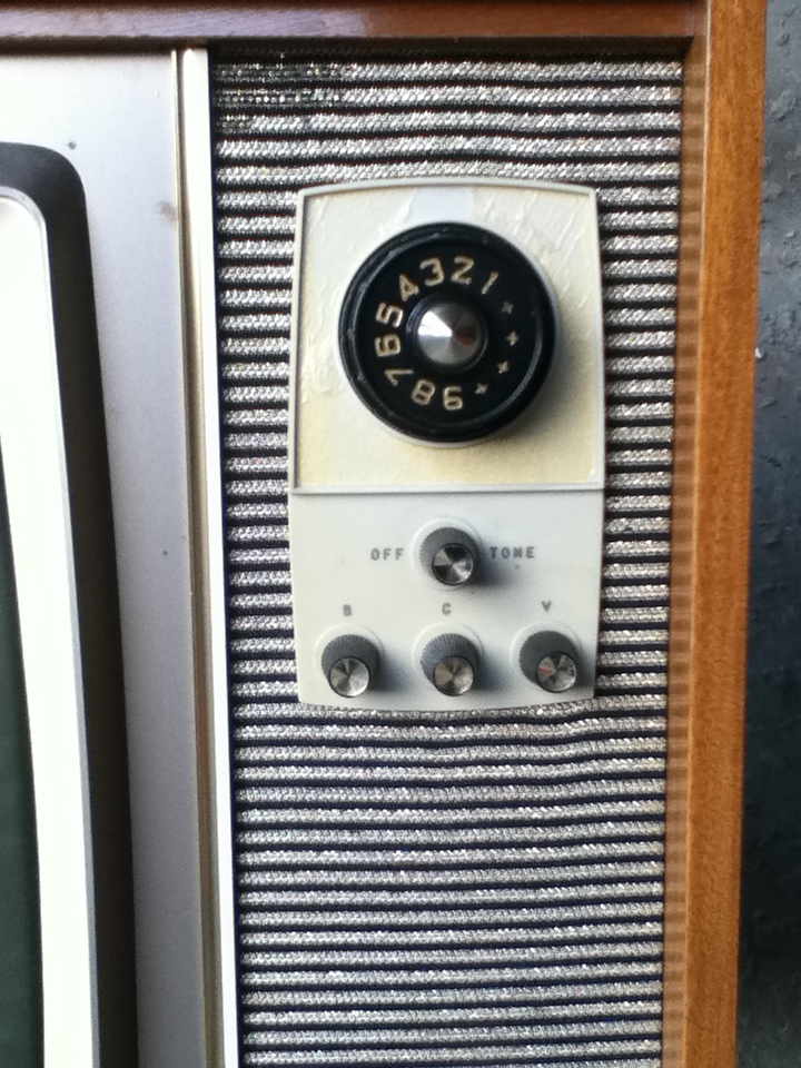
Control Panel/Tuner
Underneath top chassis

Another view
Underneath bottom chassis

First attempt at powering up..good signs apart from no vertical.

Donor chassis

Wednesday, 25 July 2012

Pye T25Y 16" Portable TV - Updated 24/5/2019

Here is a smaller set from my collection, it has a 16 inch CRT and of a hybrid construction so has valves and transistors combined together. Has a total of nine valves.
This one was manufactured around 1969 which was getting towards the end of the monochrome era. I believe that black & whites sets stopped being made here in 1973 with the advent of colour just around the corner.
These were popular sets in their day and were pretty reliable, this one I've owned for many years and recall getting it for free. I did work on it briefly back in 2003 and from memory had some problems with the vertical and didn't go any further with it.
Nice and easy to work and nothing in these are too difficult to get at. The flyback sections uses a compactron valve 38HE7. This valve has the boost diode and line output pentode all in one. A lot of American sets used valves like this in their portables and larger sets as well.
More below...

Front


Rear

Chassis hinged down

Close up of line output/EHT section

Valve/Transistor locations.
I decided that for my first project for the resuming hobby and the new workshop being all setup and ready to go was to resume repairing this and to get it working properly this time around.

Upon applying some mains after its long slumber the set came to life displaying a crappy raster crackling audio and some arcing noise accompanied by hissing EHT which turned out to be the lead from the line output transformer to the top cap of the DY87 was about to fall apart. Once that was repaired and sorted I moved on to looking into the vertical to see what was up there.

Discovered pretty quickly with the aid of the circuit that some twat (not me) had attempted to repair it by putting wrong value components in place not to mention a cap tacked across pins on ECL85 on the print side to try and compensate for whacked out frame operation which wasn't even meant to be there! So the putting the correct parts back in place and removing the bodged capacitor, the vertical was starting to look more normal again and height/linearity controls now worked properly!

Now moving onto the horizontal, it worked but the sync was poor and lock was very touchy etc and it didn't take long to discover that the phantom bodger had been there as well changing component values and linking things out again around the ECF802. I wonder what the logic behind doing this and obviously there was some fault that kept this person experimenting around with the circuit and the reasons why - who knows? Putting the right value components back in this area made things a bit happier and more stable and I could now obtain good horizontal sync and lock.

With these two areas sorted I then focused on the resistors that were used in this model and several others. These mustard bodied types are notorious for going high ie 47k reading 70k, 100k reading 180K etc so I make a point of checking all of them and replacing and this was no exception as I ended up changing nearly all of them, I probably didn't have to due to tolerances within the circuit but as I have a 'ton' of NOS resistors and paranoid about old crappy resistors! Its more a piece of mind thing knowing that they've been done. I did leave one or two in there that weren't in any crucial positions and did notice slight improvement as I methodically put new ones in and tested the set in between.

Once I'd done the resistor-rectomy, then removed the leaky/aged old can multi section filter capacitor and fitted replacements using three separate ones. Went through and replaced other old capacitors that looked a bit tired or were not reading right on the cap tester.

Things were now starting to look quite good by this stage so I set about cleaning the case and the front panel/glass etc when the picture vanished...Hmm ok what did I do?? A bit of probing and it returned. Swing the chassis up - no picture, swing it down - picture! Turned out to be a poor solder joint on tag strip in the fly back area probably done by me as I did work on that bit in the past. Then the picture began to fade away at will now - what the heck! Glancing at the filament on the CRT it was dimming up and down. This was an intermittent break in one of the filament wires so fixed that and then the other filament pin terminal decided to break off on tube neck socket!

A few other things went wrong as they do put a wrong value resistor in and was greeted with magic smoke from it the moment I applied power, slipped with the meter probe and blew up the 2nd vision IF Bf137 transistor, burnt the side of my hand a little on the baking 38HE7 during a moment of being careless- man those things get super toasty hot! But not too many hiccups really.

Once I had the set running stable, went to set the picture up using the test pattern and got it reasonably well adjusted there's a slight geometry error horizontally but not going worry about that after all its a 50 year old TV. The yoke correction rings have been adjusted to best as possible.

So after all that and taking 15 years to finally fix this thing,we now have working usable TV! The photos don't do the image justice its bright, sharp with good contrast so the CRT is showing no signs of any issues.

I'll run it over the next weeks to see if any further teething issues crop if but overall am happy with the outcome and feel a sense of achievement on this since it was probably one of the very first valve sets I decided to restore back in the 2000's.

Final Result - The photo doesn't do the picture quality justice.


The pile of worn out/dead parts

Birds Eye view - Most resistors/capacitors replaced.


Monday, 9 July 2012

Pye Marketing News August 1974

I was given some very rare New Zealand Pye Factory News Bulletins from the mid 1970's to early 1980's so naturally I thought the best place to scan and post them up was here!

This one is about the release of the Pye Vidmatic CT102 Colour Television.

Many thanks to Graham Street who kindly donated these to me.


Thursday, 21 June 2012

Early Television History in New Zealand

1949 - Departmental Committee established to advice the Government on overseas television developments.

1951 - Canterbury University School of Engineering conducting experiments with closed circuit TV.

7th March 1951 - NZBS first official demonstrations for Waring Taylor St studios in Wellington.

May 1952 - Canterbury Engineering School TV transmissions using callsign ZL3XT.

1952 - Departmental Committee recommended the adoption of the 405-line system of transmission.

23rd February 1952 -  First test signals called "1YA Television" in Auckland.

1953 - The NZ Radio and Electrical Trades Federation annual conference in Christchurch where delegates were invited to view a demonstration of Television as operated by the Canterbury School of Engineering.

27th November 1953 - HMV in Wellington gave a public demonstration of Television with equipment made by Collier & Beale.

1953/54 - PYE brought to New Zealand a complete television transmission station for the Queen's Royal Visit.

January 1954 - PYE demonstrated television equipment at the Wellington Royal Show and later at Auckland in April 1954.

1954 - Harlequins versus Barbarians Rugby Match at Waihi's Rugby Park was televised by Akrad Engineers as and outside broadcast and sent to sets around the field and local hospital.

Early 1957 - Bell demonstrated closed circuit TV at the Auckland Birthday Carnival at Western Springs. Similar equipment was demonstrated in Dunedin later that year.

May 1957 - Bell's first TV broadcasts on air using ZL1XQ callsign.

From July 1957 Bell's transmissions are regular for about two hours a night, four nights a week to an estimated 100 sets.

August 1958 - Government announcement that when Television is introduced in New Zealand it will be the 625 line system.

November 1958 - NZ Television Society is formed.

March 1959 - Bell TV has adverts.

April 1959 - Bell had produced the first two commerical TV models for sale.

May 1959 - First official broadcast by New Zealand Broadcasting Service from Shortland St "NZBSTV Channel 2"

December 1959 - An initial run of 300 black & white PYE 201T 21 inch television produced at the Akrad Waihi factory.

28th January 1960 - Government announced that the NZBS would operate a national TV service starting in Auckland.

1st June 1960 at 7:30pm - NZBS TV service commenced in Auckland (for 4 nights a week).

1st August 1960 - First TV licences on sale at 4 pounds per annum.

October 1960 - NZBS TV on for 5 nights a week.

September 1960 - Bell TV services ceased (except for a short re-activation period in early 1961 when a fire in the NZBS facilities at Shortland St caused a shutdown there).

1st January 1961 NZBS began transmitting 18 hours per week.


Here is an article from the NZ Herald on Monday 22nd June 1959:

                                                           600 TV Sets Already Sold in City

About 600 people have brought television receivers in the greater Auckland since they were put on sale in shops on March 12. But since the Government introduced tariff control on the picture tubes on February 9, the most any firm has been able to import is 100 tubes.
Now the demand for sets is considerably in excess of the supply.
"We cannot keep up with it" said one of the large manufactures. "Right now, it will take 12 months from the time of the order for a set to be delivered."
                                                                   Go-Ahead Awaited
"If we could get the go ahead from the Government we could have things rolling again in three weeks. There need be no lack of entertainment either.
"People are buying sets now to see Channel Two, 1YA, once a week and Channel Six, transmitted by the Bell Radio-Television Corporation, three times a week.
Their programmes are experimental, but they are a novelty.
"Furthermore 1YA could put on a programme every day right now. It has two studio cameras. a film transmitter with a vast store of National Film Unit material and a pretty good announcer. The whole industry is ready to go."
                                                                      Prices Increased
About 200 retail shops are selling television sets in greater Auckland. The post office is keeping a record of sales so that, when the comes it can call for licences, which are not yet required.
After they went sale, prices of 17-inch sets rose from 135 pounds to 151 pounds and 21-inch sets from 185 pounds to 208 pounds. This retailers said, was because every set sold required at least one call back. With only short terms of transmission on four nights, it was difficult to adjust sets and serials and teach customers how to 'drive' the receivers. Usually a customer had to be visited three times after he bought a set. The original cost estimate has to be raised.


Saturday, 28 April 2012

Colour TV Advertising/Brochures

I recently got a box full of old television service information and whilst sifting through it all I came across these old colour TV brochures.
Any New Zealand TV set advertising I consider quite rare as most of sort of thing would have been disposed of many years ago.
Just to note with the Pye brochure, the second side shows the re-badged Philips K9 sets and thankfully someone has written a date of 10/1973 on it. The two Pye sets on the first side are the early CT101 chassis, now virtually extinct.
The other brochure showing the AWA Deep Image set were actually re-badged Thorn TX574/3500 chassis.
This particular model is one TV I would love to come across as my earliest childhood memories were watching one of these but also now these have pretty much gone too.
It wasn't very reliable though, I remember every month or so a white TISCO van would turn up and a man would come in, pull the back off and change a board which would get the thing going again for a while. It got nursed along until about 1982 when Dad decided one night after it died halfway through the news, that it was time to buy a new TV.

Anything else I come across in the future like this will also be put here. Enjoy!


Black and White TV Advertising/Brochures

I recently got a box full of old television service information and whilst sifting through it all I came across a Home & Appliance Servicing Trade newspaper from April of 1965 and was pleased to find some TV advertising in it.
From this I can now accurately date my Admiral TV as one of the adverts shows a similar version of my set.
Any New Zealand TV set advertising I consider quite rare as most of sort of thing would have been disposed of many years ago.
The following has been scanned from that newspaper. Anything else I come across in the future will also be put here. Enjoy!

My Admiral is the basically same as the "Berwick" model apart from it being a console without the built in AM tuner.             


Tuesday, 17 April 2012

AWA Murphy 23" (34 Series) Super Signal TV ***Finished 27/12/2012***

I actually got this set around November of 2011 and kept on forgetting to put it up on here until now.
Its currently undergoing a slow restoration in small stages, time being the factor at the moment.

So far I've replaced the critical components in the flyback section, as all the wax capacitors were leaky and resistors were way off as well. Also the1B3GT EHT rectifier valve was also gassy so this didn't help things initially and there was also a brightness problem due to the picture tube being cutoff, cause insufficient grid volts caused by leaky caps so after fixing that it now has a picture of sorts.

This early chassis was based on an Australian design and was known as the '35' series and said to be a good performer. Several variants of this chassis were used in all AWA & Murphy sets of the time.

There are an awful lot of resistors and caps to be changed so its going to take some time. The mustard coloured resistors used in this are all way off, like the Pye T22X they will be replaced.

I've started a video diary on YouTube in regards to this set, here is the link -  http://www.youtube.com/watch?v=8CThn6yz8fE&feature=g-upl&context=G2c1cf0aAUAAAAAAATAA

Thats all on this one for now, I'll post with updates as progress is made.
The first few photos were taken with my new Ipod touch 4G at the time, image quality is ok, but the digital camera is far better.

8/6/2012 - Some slow progress has been made on this set, I've replaced a handful of components around the EHT/flyback section, all the resistors and low value electrolytics were well past their use by date, no wonder the width was lacking in size initially. Also worked on the vertical section as well, replaced a number of drifted resistors and leaky wax capacitors. So the result is now a watchable picture, not bad considering the rest of the chassis is still pretty much 80% original. So once I start replacing more parts, things should start improving. There is an issue with the top linearity, the control is at one end and thats the best I can get it for now, but no doubt theres another resistor or cap thats way off value.
So thats all for now folks! See the recent pictures added.

27/12/2012 (Photos Added) -  Finally this set is done! All cleaned up cabinet wise, fully re-capped and almost all the resistors too. The resistors that were in this were off and some of them had even drifted oddly enough to the next preferred value, which made me wonder if they were incorrectly marked while being manufactured...who knows? But at least they're out of there and won't cause any further problems.

The restoration took longer than expected, I just kept plugging away at it slowly so rather relieved that its come to an end.

But... I did have a couple of problems along the way...The first was intermittent hum bars that would come and go at will, at the time I thought it was just some of the old caps that were still in place, but after replacing all them and the rectifier diodes the hum bars were still there.

Scoping the B+ rails one of them clearly showed this 'blip' of noise moving along in time with the hum bar on the screen.

My next thought turned to the valves, thinking that maybe one of them had an internal short possibly due to the filament supply leaking AC across internally to somewhere it shouldn't be. As it turned out I found 'several' of them with multiple shorts the 6EB8 video output valve being the worst!
Once I replaced the crook valves and powered on again, the hum bars had vanished.

The next problem was towards the end of wrapping this up, I went through all the adjustments including the horizontal oscillator. Got that all done, had the picture all centered and locked nicely, powered the set on the next night from cold and found the sync to be way off.

After about 30 seconds the sync locked in again but the picture was way off to one side and I could see it slowly creeping back into line, after about 5 minutes it was normal again.

My thoughts about this turned to one of two things, faulty mica caps in the circuit as there were a couple and there was one in series with the hold control and the grid of the 6CG7 or the valve itself.

I changed that mica cap as it was well below its value of 330pf, this didn't really improve things so popped in another 6CG7 and problem solved!
So much for the original valve testing OK! I think in future I'll have some good know substitute ones handy for future niggly things like this.

So now its all back together and running very well, despite the CRT being on the weak side it still gives a very nice picture.

This is the first time I have overhauled one of these particular AWA/Murphy 34/35 series and have to say the contrast and definition is really good. I guess a good circuit design plays a part in this as well. If the picture tube was good the results would stunning I bet.
I've got two more variants of this to do so looking forward to getting to those eventually. They're both consoles and one of them is mint and low use so that should really respond to some work.

Now I can move onto something else, have plenty more to choose from...unsure what one I'll start on next... as for this one...The End!

Restoration Complete 27/12/2012. First photos and progress below.


Initial Look

First glance inside


Underside of the chassis...Look at all those crusty old resistors and caps.They're just waiting to cause trouble!
New boost capacitors installed. These are crucial to ensure the line output stage operates properly.
A picture of sorts...at least its working, well kind of!

 8/6/2012 - A far better picture than last time.

 8/6/2012 - Vertical section with some new components

  8/6/2012 - Components changed in the flyback/EHT area - I cheated with the old component legs and used wound sections of solid wire to solder the new ones into. Quite neat, I've seen in this some old Philips electronics.


Chassis all completed underneath. A mixture of NOS components and some modern types.

  The dead bits/organs

 Chassis all clean with shiny valves.

 Cleaned up cabinet and front panel/glass.

Excerpt from the original "Twilight Zone Series"