Here is a smaller set from my collection, it has a 16 inch CRT and of a hybrid construction so has valves and transistors combined together. Has a total of nine valves.
This one was manufactured around 1969 which was getting towards the end of the monochrome era. I believe that black & whites sets stopped being made here in 1973 with the advent of colour just around the corner.
These were popular sets in their day and were pretty reliable, this one I've owned for many years and recall getting it for free. I did work on it briefly back in 2003 and from memory had some problems with the vertical and didn't go any further with it.
Nice and easy to work and nothing in these are too difficult to get at. The flyback sections uses a compactron valve 38HE7. This valve has the boost diode and line output pentode all in one. A lot of American sets used valves like this in their portables and larger sets as well.
More below...
 |
| Front |
 |
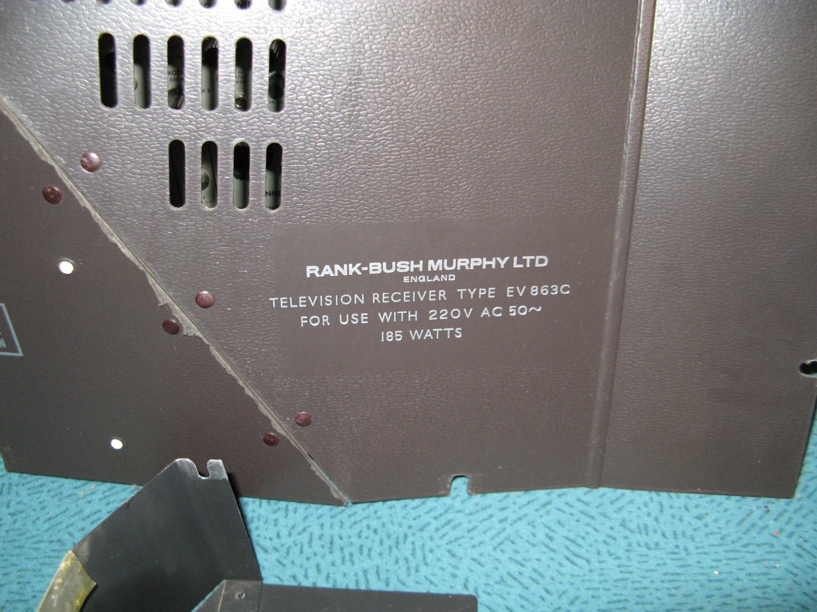
| Rear |
 |
| Chassis hinged down |
 |
| Close up of line output/EHT section |
 |
| Valve/Transistor locations. |
I decided that for my first project for the resuming hobby and the new
workshop being all setup and ready to go was to resume repairing this and to get it working properly
this time around.
Upon applying some mains after its long slumber the
set came to life displaying a crappy raster crackling audio and some
arcing noise accompanied by hissing EHT which turned out to be the lead
from the line output transformer to the top cap of the DY87 was about to
fall apart. Once that was repaired and sorted I moved on to looking
into the vertical to see what was up there.
Discovered pretty quickly
with the aid of the circuit that some twat (not me) had attempted to
repair it by putting wrong value components in place not to mention a
cap tacked across pins on ECL85 on the print side to try and compensate
for whacked out frame operation which wasn't even meant to be there! So
the putting the correct parts back in place and removing the bodged
capacitor, the vertical was starting to look more normal again and
height/linearity controls now worked properly!
Now moving onto the horizontal, it worked but the sync was poor and
lock was very touchy etc and it didn't take long to discover that the
phantom bodger had been there as well changing component values and
linking things out again around the ECF802. I wonder what the logic
behind doing this and obviously there was some fault that kept this
person experimenting around with the circuit and the reasons why - who
knows? Putting the right value components back in this area made things a
bit happier and more stable and I could now obtain good horizontal sync
and lock.
With these two areas sorted I then focused on the resistors that were
used in this model and several others. These mustard bodied types are
notorious for going high ie 47k reading 70k, 100k reading 180K etc so I
make a point of checking all of them and replacing and this was no
exception as I ended up changing nearly all of them, I probably didn't
have to due to tolerances within the circuit but as I have a 'ton' of
NOS resistors and paranoid about old crappy resistors! Its more a piece
of mind thing knowing that they've been done. I did leave one or two in
there that weren't in any crucial positions and did notice slight
improvement as I methodically put new ones in and tested the set in
between.
Once I'd done the resistor-rectomy, then removed the leaky/aged old
can multi section filter capacitor and fitted replacements using three
separate ones. Went through and replaced other old capacitors that
looked a bit tired or were not reading right on the cap tester.
Things were now starting to look quite good by this stage so I set
about cleaning the case and the front panel/glass etc when the picture
vanished...Hmm ok what did I do?? A bit of probing and it returned.
Swing the chassis up - no picture, swing it down - picture! Turned out
to be a poor solder joint on tag strip in the fly back area probably
done by me as I did work on that bit in the past. Then the picture began
to fade away at will now - what the heck! Glancing at the filament on
the CRT it was dimming up and down. This was an intermittent break in
one of the filament wires so fixed that and then the other filament pin
terminal decided to break off on tube neck socket!
A few other things went wrong as they do put a wrong value resistor
in and was greeted with magic smoke from it the moment I applied power,
slipped with the meter probe and blew up the 2nd vision IF Bf137
transistor, burnt the side of my hand a little on the baking 38HE7
during a moment of being careless- man those things get super toasty
hot! But not too many hiccups really.
Once I had the set running stable, went to set the picture up using
the test pattern and got it reasonably well adjusted there's a slight
geometry error horizontally but not going worry about that after all its
a 50 year old TV. The yoke correction rings have been adjusted to best
as possible.
So after all that and taking 15 years to finally fix this thing,we
now have working usable TV! The photos don't do the image justice its
bright, sharp with good contrast so the CRT is showing no signs of any issues.
I'll run it over the next weeks to see if any further teething issues
crop if but overall am happy with the outcome and feel a sense of
achievement on this since it was probably one of the very first valve sets I decided to restore back in the 2000's.
 |
| Final Result - The photo doesn't do the picture quality justice. |
 |
| The pile of worn out/dead parts |
 |
| Birds Eye view - Most resistors/capacitors replaced. |